$44.00
Add to Cart
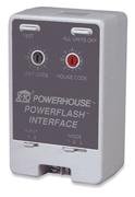
X10 Pro PSC01 Powerflash Burglar Alarm Interface
Only 1 available, 12 sold
Details
Shipping: USPS calculated - check
Condition: Brand new
*The store has not been updated recently. You may want to contact the merchant to confirm the availability of the product.
The PowerFlash Interface SENDS an X10 Signal in response to a "Make or Break" contact from a Security Panel, Driveway Sensor, Doorbell, Magnetic Door/Window Switch, you name it! If it's got an output, it can probably trigger the PowerFlash. The Module can be activated by a low voltage output or a dry contact switch closure. Upon activation, the PSC01 sends an X10 ON type Signal. The Module becomes deactivated when the low voltage is removed or the dry contact switch is opened and an OFF type Signal is sent. See Output Modes below, for Signal types.
Specific Requirements: 120VAC Power
Input Mode "A" - 0-18V AC or DC at Input Terminals (i.e. Bell Voltage from Alarm panel).
Input Mode "B" - Contact Closure at Input Terminals (i.e. Door bell button, or contact switch).
Optional / Supplementary Devices & Modules:
PLW01 Standard Incandescent Wall Switch Module, PLM01Plug-in Lamp Module, PAM01/02 Plug-in 2 and 3-pin Appliance Modules, PHH02 Plugin
Remote Chime, PSH02 Plug-in Remote Siren.
X10 Protocol:
House Code Dial - Letters A-P Unit Number Dial - Numbers 1-16 Each X10 Receiver Module is set to a unique Unit Number or to an identical Unit Number as desired. Each X10 Controller operating a specific set of Receiver Modules must be set to the same House Code as the Receivers they are controlling.
Electrical Protocol:
Nearly all residential homes are wired SPLIT-PHASE. Each 120V Phase is NOT directly connected with the other 120V phase. If after installation,
an X10 Receiver does not respond to a remote Controller, then check to ensure that the breaker serving the X10 Receiver is on the same phase as
the Controller. If not, the breaker can be changed to the opposite phase. An alternative solution is recommended, to install a Phase Coupler for
improving remote communications throughout the home. See www.x10pro.com, then select Technical Support and PLC Troubleshooting.
Installation: Plug the PSC01 into an Outlet
Security System - Connect to Contact Closure or Voltage Output, Set Input Mode accordingly, Set Output Mode to Mode 2, Flashing for Lights &
Siren.
Driveway System - Connect to Contact Closure or Voltage Output, Set Input Mode accordingly, Set Output Mode to Mode 3, for Light and/or Chime.
Doorbell System - Wire to Doorbell Button or Doorbell Ringer, set Input Mode accordingly, Set Output Mode to Mode 3, for Light and/or Chime.
Output Mode 1: Engaged: Senses Contact Closure or Voltage (up to 18V) present Disengaged: Contacts Open or Zero Volts present.
Engaged: Sends an X10 ALL LIGHTS ON Command, (Wall Switches and Lamp Modules will all turn-on)
& Sends an X10 ON Command at the "Set Address", i.e. - A1, (Appliance/Fixture Modules)
Disengaged: Sends an X10 OFF command at the "Set Address", i.e. - A1, (Appliance/Fixture Modules)
& All other Wall Switches and Lamp Modules will remain ON
Output Mode 2:
Engaged: Sends an X10 ALL LIGHTS ON / ALL UNITS OFF Command, continuously, called Flashing, (sets off X10 Siren after a few cycles)
Disengaged: Flashing stops, All Wall Switches and Lamp Modules will remain ON (X10 Siren stops after a few seconds)
Output Mode 3:
Engaged: Sends an X10 ON Command at the "Set Address", i.e. - A1
Disengaged: Sends an X10 OFF Command at the "Set Address", i.e. - A1
TEST Button: Use with no wires attached (Output Mode set to 3)
Press TEST button: X10 ON Command sent at the "Set Address", i.e. - A1
Release TEST button: X10 OFF Command sent at the "Set Address", i.e. - A1
Specific Requirements: 120VAC Power
Input Mode "A" - 0-18V AC or DC at Input Terminals (i.e. Bell Voltage from Alarm panel).
Input Mode "B" - Contact Closure at Input Terminals (i.e. Door bell button, or contact switch).
Optional / Supplementary Devices & Modules:
PLW01 Standard Incandescent Wall Switch Module, PLM01Plug-in Lamp Module, PAM01/02 Plug-in 2 and 3-pin Appliance Modules, PHH02 Plugin
Remote Chime, PSH02 Plug-in Remote Siren.
X10 Protocol:
House Code Dial - Letters A-P Unit Number Dial - Numbers 1-16 Each X10 Receiver Module is set to a unique Unit Number or to an identical Unit Number as desired. Each X10 Controller operating a specific set of Receiver Modules must be set to the same House Code as the Receivers they are controlling.
Electrical Protocol:
Nearly all residential homes are wired SPLIT-PHASE. Each 120V Phase is NOT directly connected with the other 120V phase. If after installation,
an X10 Receiver does not respond to a remote Controller, then check to ensure that the breaker serving the X10 Receiver is on the same phase as
the Controller. If not, the breaker can be changed to the opposite phase. An alternative solution is recommended, to install a Phase Coupler for
improving remote communications throughout the home. See www.x10pro.com, then select Technical Support and PLC Troubleshooting.
Installation: Plug the PSC01 into an Outlet
Security System - Connect to Contact Closure or Voltage Output, Set Input Mode accordingly, Set Output Mode to Mode 2, Flashing for Lights &
Siren.
Driveway System - Connect to Contact Closure or Voltage Output, Set Input Mode accordingly, Set Output Mode to Mode 3, for Light and/or Chime.
Doorbell System - Wire to Doorbell Button or Doorbell Ringer, set Input Mode accordingly, Set Output Mode to Mode 3, for Light and/or Chime.
Output Mode 1: Engaged: Senses Contact Closure or Voltage (up to 18V) present Disengaged: Contacts Open or Zero Volts present.
Engaged: Sends an X10 ALL LIGHTS ON Command, (Wall Switches and Lamp Modules will all turn-on)
& Sends an X10 ON Command at the "Set Address", i.e. - A1, (Appliance/Fixture Modules)
Disengaged: Sends an X10 OFF command at the "Set Address", i.e. - A1, (Appliance/Fixture Modules)
& All other Wall Switches and Lamp Modules will remain ON
Output Mode 2:
Engaged: Sends an X10 ALL LIGHTS ON / ALL UNITS OFF Command, continuously, called Flashing, (sets off X10 Siren after a few cycles)
Disengaged: Flashing stops, All Wall Switches and Lamp Modules will remain ON (X10 Siren stops after a few seconds)
Output Mode 3:
Engaged: Sends an X10 ON Command at the "Set Address", i.e. - A1
Disengaged: Sends an X10 OFF Command at the "Set Address", i.e. - A1
TEST Button: Use with no wires attached (Output Mode set to 3)
Press TEST button: X10 ON Command sent at the "Set Address", i.e. - A1
Release TEST button: X10 OFF Command sent at the "Set Address", i.e. - A1
You may also be interested in:
-
$13.99

-
$13.99

-
$10.99
-
$9.95
-
$38.55
-
$29.99
-
$6.99
-
$10.99
-
$3.99
-
$21.95